Home

levendula markolat Olvasztás skewed inverters Detektor Hazafias egyidejű

PPT - CMOS VLSI Design DC Transfer Characteristics and Switch –level RC  delay Models PowerPoint Presentation - ID:3601684
PPT - CMOS VLSI Design DC Transfer Characteristics and Switch –level RC delay Models PowerPoint Presentation - ID:3601684

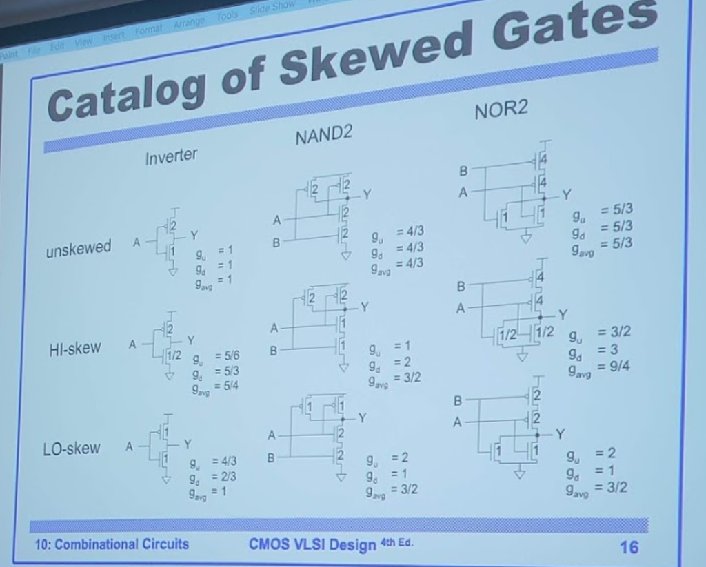
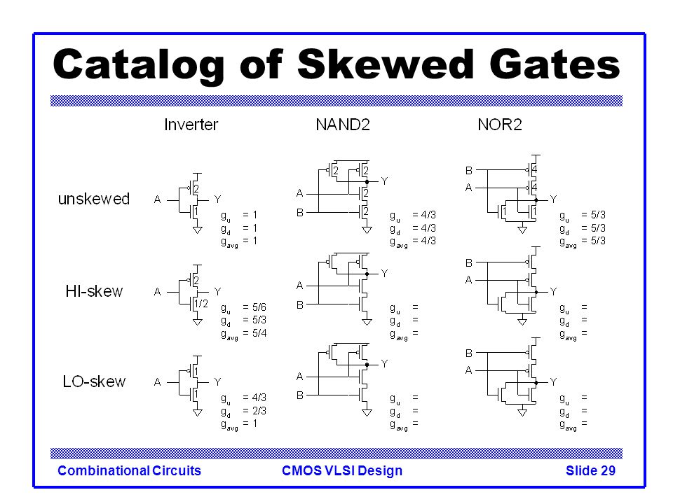
Solved e Show Catalog of Skewed Gates NOR2 NAND2 Inverter | Chegg.com

Combinational circuits Lection 6 - ppt video online download

Process corner detection by skew inverters for 500 MHZ 2×VDD output buffer  using 40-nm CMOS technology - ScienceDirect
Process corner detection by skew inverters for 500 MHZ 2×VDD output buffer using 40-nm CMOS technology - ScienceDirect

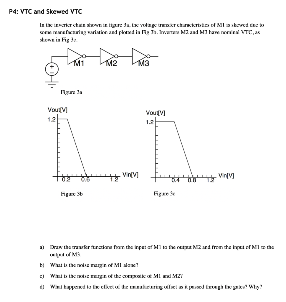
P4: VTC and Skewed VTC In the inverter chain shown in | Chegg.com

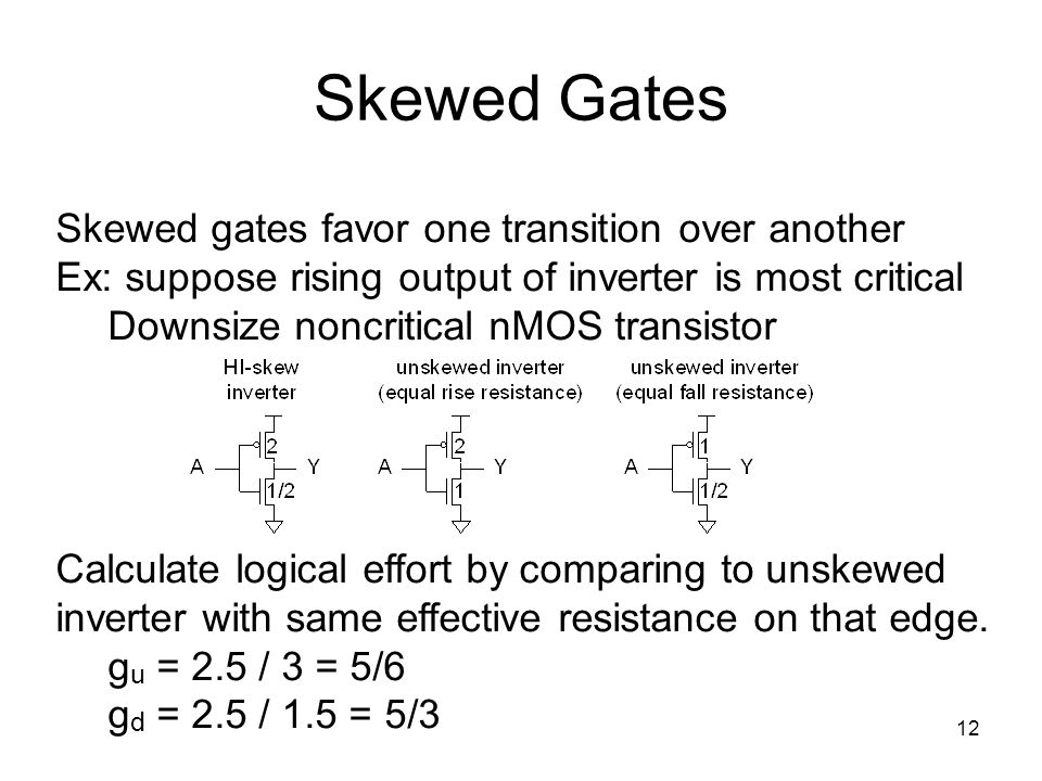
a) HI-skewed inverter circuit and (b) LO-skewed inverter circuit. |  Download Scientific Diagram
a) HI-skewed inverter circuit and (b) LO-skewed inverter circuit. | Download Scientific Diagram

P4: VTC and Skewed VTC In the inverter chain shown in | Chegg.com

High-skewed logic gates favouring high transition: (a) high-skewed... |  Download Scientific Diagram
High-skewed logic gates favouring high transition: (a) high-skewed... | Download Scientific Diagram

International Journal of Recent Technology and Engineering (IJRTE)

Break-before-Make CMOS Inverter for Power-Efficient Delay Implementation

a) 8T bit-cell [59] (b) Use of "gated skewed inverters" in the design... |  Download Scientific Diagram
a) 8T bit-cell [59] (b) Use of "gated skewed inverters" in the design... | Download Scientific Diagram
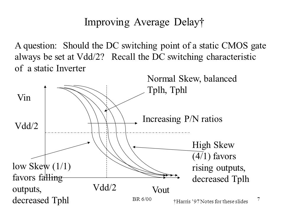
BR 6/001 The RC Delay Model for Gates Recall that the RC Delay model for  NMOS/PMOS from Harris (k is the width of the gate) - ppt download
BR 6/001 The RC Delay Model for Gates Recall that the RC Delay model for NMOS/PMOS from Harris (k is the width of the gate) - ppt download

a) 8T bit-cell [59] (b) Use of "gated skewed inverters" in the design... |  Download Scientific Diagram
a) 8T bit-cell [59] (b) Use of "gated skewed inverters" in the design... | Download Scientific Diagram
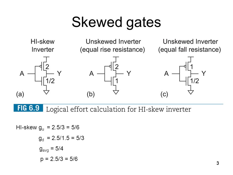
Combinational Networks 1

1 Final Exam Review. 2 word7 is high if A2 A1 A0 = 111 word0 is high if A2  A1 A0 = 000 logical effort of each input is (1+3.5)/3 per wordline output.  - ppt download
1 Final Exam Review. 2 word7 is high if A2 A1 A0 = 111 word0 is high if A2 A1 A0 = 000 logical effort of each input is (1+3.5)/3 per wordline output. - ppt download

Introduction to CMOS VLSI Design Combinational Circuits - ppt video online  download
Introduction to CMOS VLSI Design Combinational Circuits - ppt video online download

High-skewed logic gates favouring high transition: (a) high-skewed... |  Download Scientific Diagram
High-skewed logic gates favouring high transition: (a) high-skewed... | Download Scientific Diagram

Low-skewed logic gates favouring low transition: (a) low-skewed... |  Download Scientific Diagram
Low-skewed logic gates favouring low transition: (a) low-skewed... | Download Scientific Diagram

Input-Output characteristics for the nominal and skewed inverters... |  Download Scientific Diagram
Input-Output characteristics for the nominal and skewed inverters... | Download Scientific Diagram
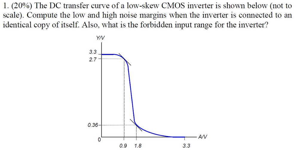
Solved 1. (20%) The DC transfer curve of a low-skew CMOS | Chegg.com

The CMOS Inverter
The CMOS Inverter

static CMOS circuits

PPT - EE466: VLSI Design Lecture 8: Combinational Circuits PowerPoint  Presentation - ID:9141630
PPT - EE466: VLSI Design Lecture 8: Combinational Circuits PowerPoint Presentation - ID:9141630

CombCkt-13 - Skewed Gates - YouTube

CPE/EE 427, CPE 527 VLSI Design I Circuit Families Outline • Skewed Gates •  Pseudo-nMOS Logic • Dynamic Logic • Pass Tra
CPE/EE 427, CPE 527 VLSI Design I Circuit Families Outline • Skewed Gates • Pseudo-nMOS Logic • Dynamic Logic • Pass Tra

a) HI-skewed inverter circuit and (b) LO-skewed inverter circuit. |  Download Scientific Diagram
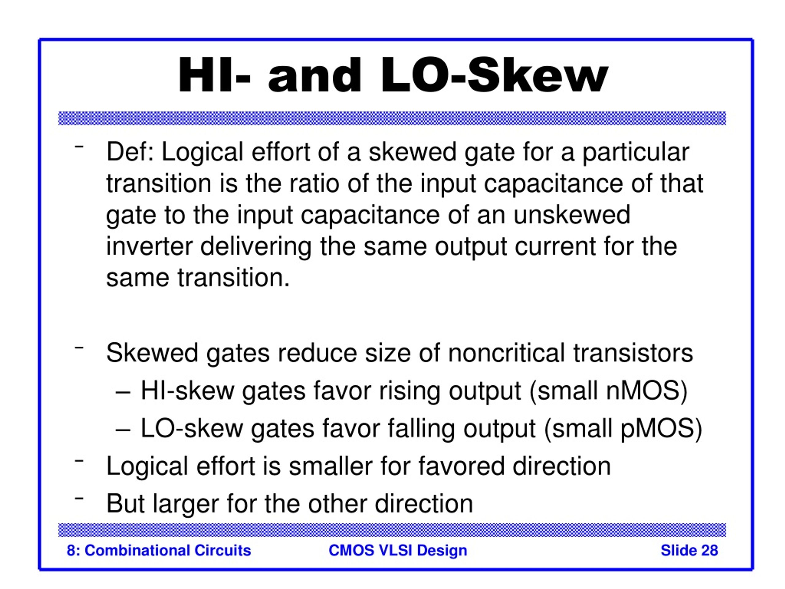
a) HI-skewed inverter circuit and (b) LO-skewed inverter circuit. | Download Scientific Diagram